Update: This post is deprecated and will no longer be updated, as the RPi Pico cannot produce stable PWM signals. For example, it may pull up a whole pair of complementary PWM signals when applying the official APIs. Consequently, this leads to catastrophic damage (i.e., shoot-through) in half-bridge applications.
Therefore, it is suggested to use MCUs specifically designed for digital-control power converters such as STM32G4 and 280049, which provide industry-level high-resolution timers.
An application for a digital-control buck converter with STM32G4 is developed and can be referenced here.
Design idea: Designing a DC/DC Converter (chopper) with the use of Raspberry Pi Pico MPU to convert input DC voltage from 0-30V to 5V to power up electronic devices such as Raspberry Pi AI Kit.
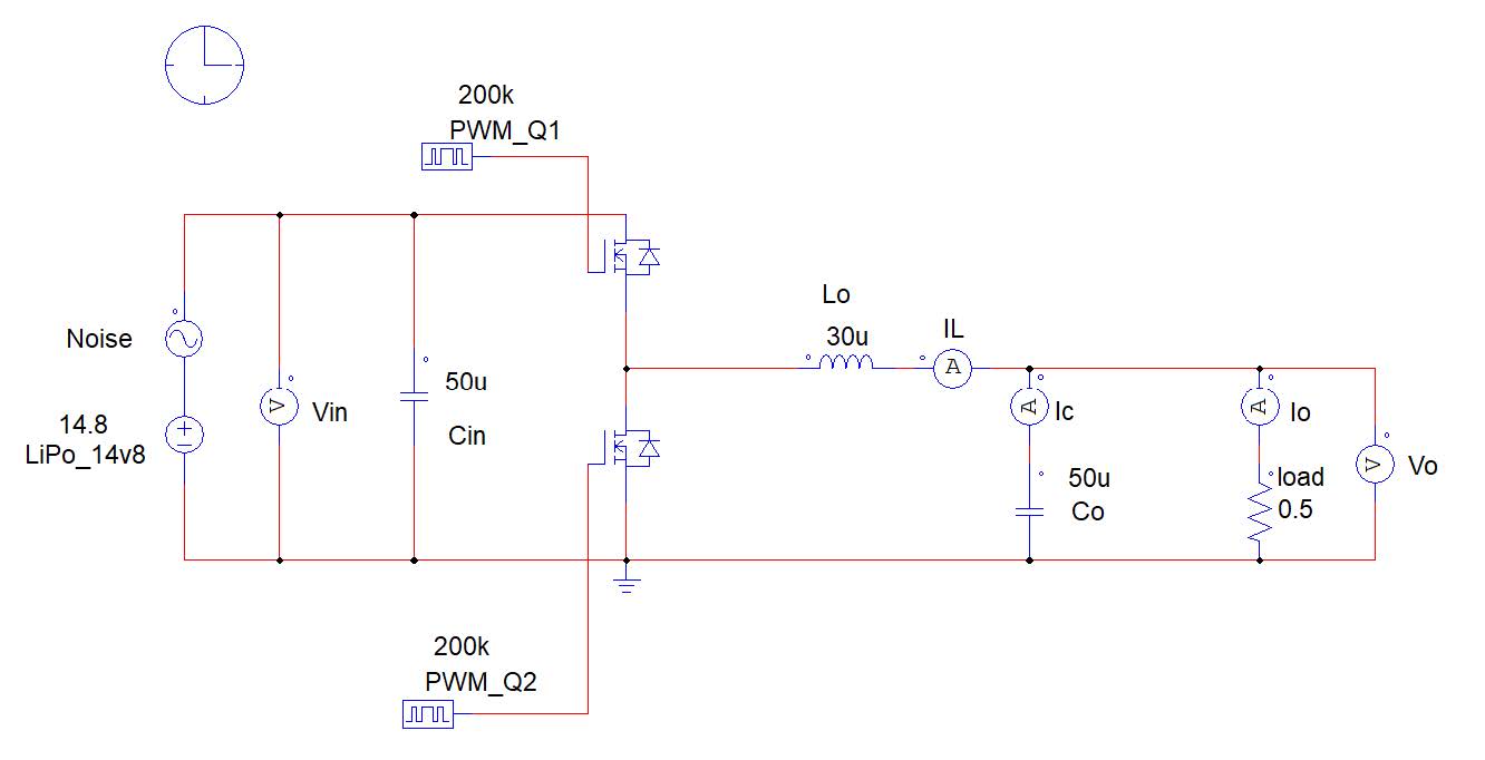
Converter Type: Synchronous Buck Converter (Synchronous Rectification/Synchronous Switching)
Input Voltage: Li-Po Battery in range of 1s-6s (Maximum 30VDC)
Output Voltage: 5VDC
Rated Power: 25W (Rated Current: 5A)
Reason for choosing Raspberry Pico as a microcontroller:
Familiar with Raspberry Pi Pico ✔
Familiar with STM32 ❌
Reference: